Someone was giving away a broken television – “it flickers” – on the local Buy Nothing group. I have a project that wants a high-quality diffusion lens, so I say “Hey, if nobody wants to try to fix it, I’ll take it” and I end up with it.
I pick it up. It’s much heavier and thinner than I expected, and higher end than I also expected, but no big deal until…
…I get home and realise it’s an OLED television, which doesn’t have the diffusion lens I want. They must’ve spent some serious money on this thing.
So I get into the paperwork, notice a couple of extra bits but skip them to get to how to assemble the stand, do so, and hook it up to see the flicker. To my surprise, actually yeah, that’s a reasonable description of what it’s doing! But it’s mostly working so maybe I can fix it. If not, oh well, my bad for not checking to make sure it’s not OLED.
Then I go through the rest the paperwork they threw in with it from 2019 when they bought it and discover:
The actual purchase receipt
The actual extended warranty proof of purchase that you need to use the extended warranty
Which says that they bought three years of extension to the two-year factory warranty which means
This goddamn thing is still under warranty.
I presume they will want it back. I have left them a message. This may be complicated by the fact they were heading out right after I picked this up, so now I’m wondering if they were going out to buy another TV.
Given how much this one may’ve cost, I’m kind of thinking it’s worth their time to take the new one back. But we’ll see.
Anybody know the proper way to test a high-voltage self-discharging capacitor?
(Don’t say Mr. Carlson’s, it’s a fine device but it doesn’t test caps like this. Will it show a leak? Yes. That’s by design.)
With a regular meter it tests in range and it’s correctly self-discharging but all that’s at meter voltage which is not exactly this thing’s operating range.
(It’s from a cabinet-fit microwave. Everything works except the magnetron doesn’t actually do anything. I hear the relay click but no zappy. So it’s probably that. But I’m not willing to replace that part because that involves breaking microwave radiation containment shields and I don’t have a microwave detector and I’m not buying one for one (1) microwave repair.)
Oh hell yeah the air-exchange vent did the thing! It’s probably not the first time but I did just roll out the code over the weekend and it’s the first time I’ve caught it doing this:
log file output showing ambient_hvac noticing the air outside is better than inside from a 2.5nm ppm standpoint, and opening the air exchange vent to let outside air into the house filtered air circulation loop
What’s happening here is that the system is reporting that indoor air was lower quality than the outdoor air by enough points that even though the temperature directly was wrong, it activated the air-exchange for five minutes anyway to help with air quality. Then it closed it down again.
ambient_hvac at work!
I probably need to fiddle with that buffer number – an indoor of 9ppm is still very good and could even have been a false reading and 4 probably isn’t better enough to care. And I don’t want to be stressing the air-exchanger. But this is all more testing phase so of course it’s going to be a little wibbly at times. I’m fine with that. What matters is: it’s working! 😀
So I spun up my air-exchange HVAC system’s test platform in “summer” more with the new air-exchanger controller board set up and programme, and it checked all the temperatures, recognised it was cooler outside than in, overrode the time-of-day basic programme and wirelessly opened the vent to bring in cooler air!
Or turned on the little lamp standing in for the vent, whatever. It’s still proof of functionality! And while it is a test platform – running in parallel to the real one – it’s still working off live data. So it’s literally as real as the production version!
the little white light means it’s working!
Indoor temperature was a warm 21.5°C, so in Summer mode, the system should trigger air exchange and bring in outdoor air to cool the house via the air exchanger. And it did! And then I put it into winter mode and it flipped back to closed, also just as it should.
SMOKE mode closes the vents too – we’ll need that in, well, smoke season.
I set smoke mode manually but again, everything else is live data, including the air exchange status display. It’s querying the board via wireless and getting the correct answer. If you unplug the hardware from power and plug it back in, it’ll see that the board reset itself to all-vents-closed and tell you, before fixing it. 😀
Indoors is 21.5°C and the software and hardware are opening the vent correctly in each mode
I also have a little bit of error handling. Just enough really? But it’s enough in that it tells you it can’t reach the board. After grabbing this capture I changed the code so it’s bold instead of ALL CAPS but it’s the same otherwise. That’s just formatting:
Anyway my plan(?) is to physically hook it up to the actual air exchanger hardware this weekend. Unless I change my mind. It’ll operate in place of a timer that’s down there at the moment, running on a set schedule that I’ve been changing a few times a year. That’s been neither optimal or fun, so having a proper way to do this – a way that actually responds to live data – is going to be pretty great and will hopefully will gain us another few percents of efficiency.
Bonus points: it’ll run off the furnace’s 24V DC system so I won’t even have to get sketchy with running electrical power to the board. All I need is one of my buck converters and it’s ready to wire up.
This is already a good system and it’s going to become a really good system and if I don’t have to flee the country it’s just going to be so nice having it here. Fuck yeah automation. This is gonna be great. 😀
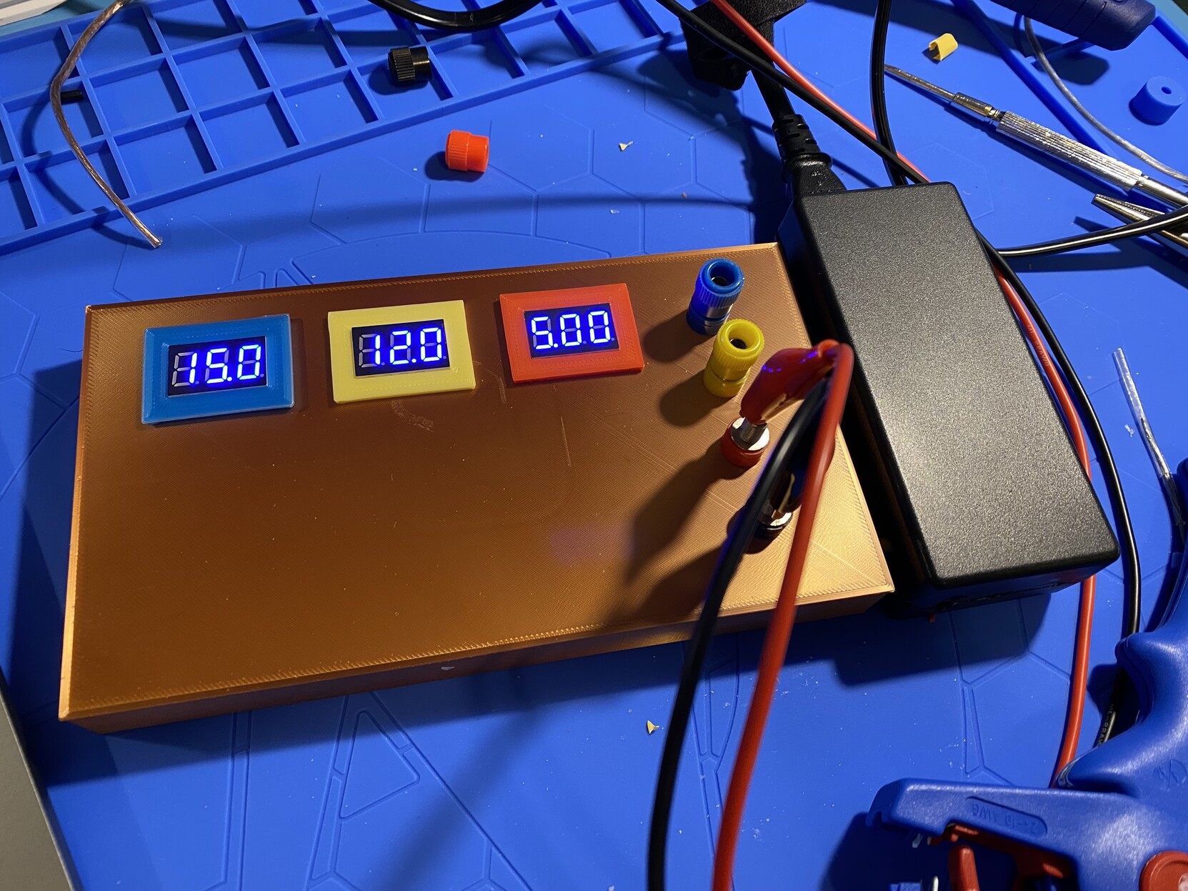
I made a thing! It’s a powered breadboard. Breadboards are experimental tools, to let you build test circuits. You can get really over the top with them – there’s a youtuber who built a simple CPU out of discreet components on breadboards and last I saw was still expanding its capabilities. But for me it’s more a learning tool.
You can buy them on eBay and Amazon but since I had a lot of parts already I built my own and it was in fact cheaper than buying one! Take that, economies of scale!
It has three power supply voltages and they’re adjustable. The copper-coloured brick and the colour coded frames is 3D printed, the voltage displays are accurate/realtime (and cheap, five for like $8, bought for this), the voltages are adjusted using buck converters (similarly cheap, already on hand), and the power supply brick was from an old Toshiba laptop. It natively supplies something like 16.3V DC – more than the 15V which is common and even then more than I’ll need for this. And since it’s meant to drive a laptop, it has lots of overhead, so everybody wins.
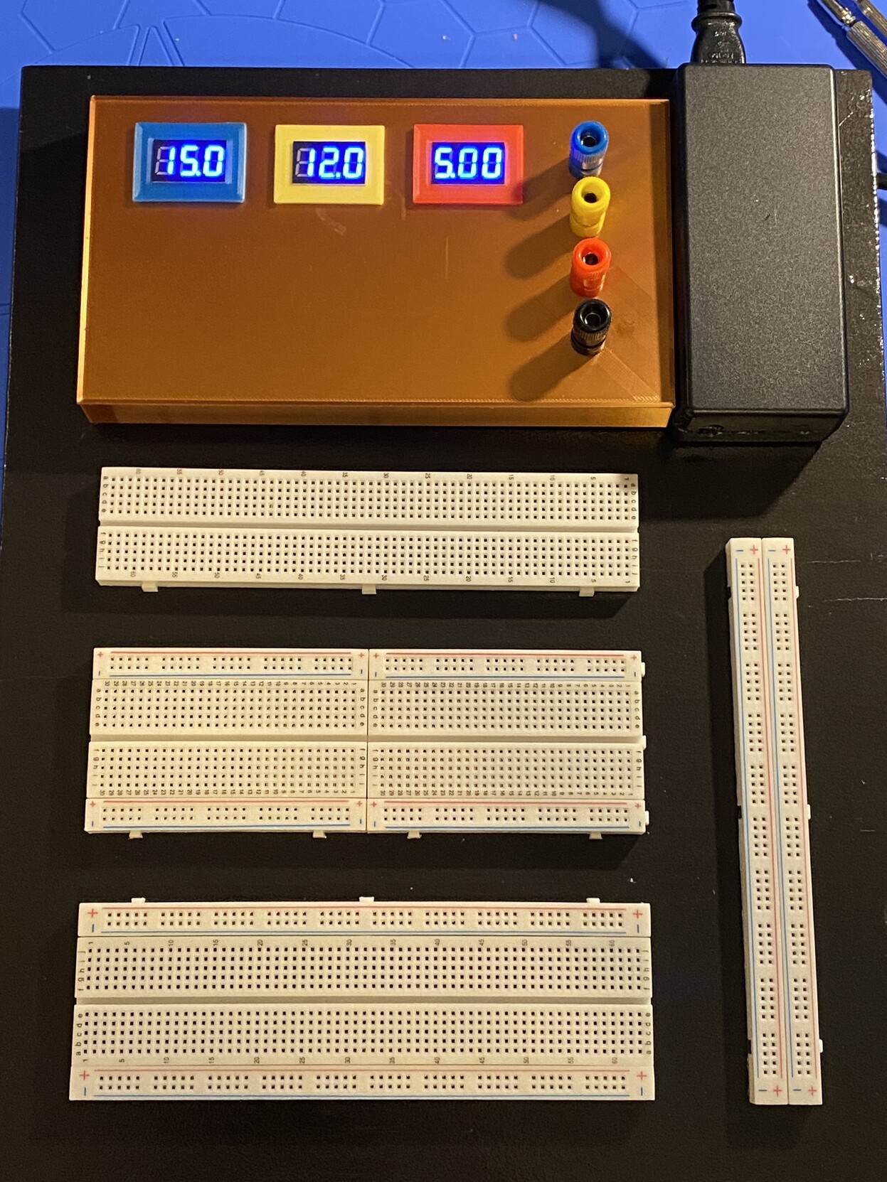
And this is the entire workboard! The black board is painted scrap from a broken-down chest of drawers, pretty much the last piece I have from that. I think it’s from the 1940s but could’ve well been the 1950s. Either way, it’s some old lumber. xD The white boards are experimenter’s boards, you can plug standard through-hole components into them and make circuits; the lines of holes marked + and – are connected through the whole line, the ones labelled with alphabet letters are connected in groups of five, aligned with the numbers on the sides.
Oh yeah, the board wanted to warp a bit so it has smoothed aluminium L-metal left over from another project on the underside for flatness and that sorted that out just fine.
The only thing I’d really do differently I think is measure the board for actual squareness. It’s not quite square and fortunately since I painted it black it’s not as big a deal, but it still bugs me just a little. xD
So I’ve got hardware now to give me software control over 1-4 air intakes, and I need to have some sort of way(s) to control all that.
But so far, here’s the thing: basically all of it is passive on the server side, too. Nothing happens if you don’t hit the UI frontend. That’s made good sense up until now, because there’s no real need, and they refresh themselves every two minutes on the client side, so you’re always getting data, and that’s absolutely all that’s been needed for all of this – until now.
I mean yeah, there’s a saved state (the current mode) and cacheing (for partial/temporary loss of connectivity) but for the most part, it’s nothing where you’re maintaining an operational state.
So now I need to figure out: do I want to keep it operating like that? As long as there’s at least one UI pane up, it would work fine. The display panels themselves would drive the entire system, every time there’s a refresh (every two minutes) check to see what the fresh air state should be, calculate it, and set it that way. You don’t even need to check whether it’s already set, sending a command that maintains the current state has no effect on the hardware, and it’d make up for any lost packets or power issues that caused a state reset.
But it does require that an interface panel is always online, or the state just… holds forever.
The alternative is some sort of server-side task that actively runs on its own, no external interfacing necessary to make it go. The exact form that takes could be all sorts of things, from a background daemon to just crontab calls every five minutes or something. You’d still need interface panel interaction, for manual open/close and for basic schedule setup, but then all panels could be offline and everything would still work, just on the server.
There’s whiffs of cooperative vs. pre-emptive multitasking arguments here from back in the day – kinda – with panel-driven state management taking the unfortunate role of cooperative multitasking. But given that, I don’t think the contest necessarily plays out the same.
I still dunno.
Of course, I have other questions to play with too, like how the basic schedule is going to be maintained and what kind of interface you have and whether it’s like some kind of time list or an array of time slots that can be toggled, and so on. Both have advantages and disadvantages and I don’t have a quick answer to that, either. But I’ll have to pick something, regardless.
Lots to think about. Definitely lots to think about.
I am finally going to get remote control going on the fresh air intake vent – with expansion for three more. (And I have plans for those relays! Or at least ideas. Ideas. Yes. At least ideas.)
It’s not much to look at right now. I mean, it’s a little block of relays with a wifi transmitter on it. But it’s arduino programmable, which means that once you find all the firmware you need you can use it to turn things on and off using commands over your LAN. If you’ve done more than I have with Arduino, I’m sure it’s really quite straightforward – it’s not conceptually difficult for me, either, it’s just been incredibly fiddly given all the many stupid little things I didn’t already know.
LinkSprite LinkNode R4
The supplied firmware wants to talk to a cloud server in order to use it. Thankfully, Steve in Colorado said fuck that and wrote some replacement code, and it works. And now I’ve learned how to use curl for REST API calls, which I’ve never done before even though it’s like normally the first thing you do instead of the zillionth.
What this is going to let me do is roll actual temperature-driven air-exchange into Summer mode in my passive/air-exchange-driven HVAC assistance system – you know, the one where the core code is on my github. This has been a blocking issue for fucking ages, and I’ve just never had the combination of time and organisation to solve it.
But now it’s fucking solved, mate.
I still have some other things to do. This is a … holy shit I just realised something. I’ve been thinking I’d need to put in a power outlet down by the furnace eventually (which means pulling a permit) just for the stupid little 5v power adaptor, but I don’t, I can draw a little off the 24V DC provision for the current timer-driven system and use a buck converter to get it down to 5V for this thing.
And this after I went to all the trouble of wiring up a mains power 5V adaptor for this thing. Joke’s on me I guess lol – <BelaLugosiVoice>this simplifies everything!</BelaLugosiVoice> xD
Anyway. Once I have software control over the external fresh air intake, I can set it up so smoke mode is always closed, winter mode is… on a schedule I guess, since you always want some fresh air. I’ll have to write something to expose that as an interface clearly. But summer mode can finally be entirely temperature driven (with some kind of minimum exchange time again of course).
Or maybe if I get a CO2 sensor added into the system, I could drive it partly based on that. All year round. Or…
…or if I had an outside air quality sensor too then relative air quality could be a trigger. Whichever is cleaner! And if I can put in more intakes then I could have them on at least three sides of the building without having to open interior walls which means I could pull from the best available source temperature…
…! Lots to think about here. Finally!
Anyway. Um. Right. So I remember:
Turning relays on and off:
curl -X POST http://[boardIP]/api/relay/X/{on|off} where X is between 0 and 3 inclusive.

Turning all relays on and off:
curl -X GET http://[boardIP]/api/relay/all/{on|off}

Status of all relays:
curl -X GET http://[boardIP]/api/relay
This is going to be so fucking cool and I’m going to have it operational before summer. 😀
eta: am I aware of possible covid-19 applications? yes. i am. this is not a medical device. but yeah. i’m aware. 😀
So if you’ve wondered what’s inside of one of those 18-port USB-C breakout interface boxes that exist under various brand names – this one being a zmuipng which is popular somehow – I have photos for you! And an assortment of notes, so this is kind of a teardown.
First, opening the box: remove the two long rubber feet by peeling them away. This will reveal two screw recesses, one under each foot. Remove the screws.
This will let you spudger the top off starting on the short sides. Lever them up alternately and it’ll come clear without too much of a fight, but be very careful about the headphone jack! It’s fragile. I broke off a bit of plastic taking this one out.
The idea solution would be to spudger out the bottom, but on my unit, that was glued in. I’m fairly convinced the assembly procedure involves installing the top board, then screwing down the daughterboard that holds the screw headphone jack (and connecting the cables), then inserting the glued (!goddammit!) bottom board, screwing it all into place, and adding the feet.
I didn’t do much with the upper board; none of the chips on it seemed to gain much in the way of temperature and there’s no obvious signs of damage. The big gold ribbons go to the lower board; the smaller white ribbon goes to a headphone jack daughterboard, which connects to the two metal posts you can see in the upper left. That’s the one you have to be careful about.
There are two of VLI VL103R-Q4, another crab logo chip, this one an RMC RTS5411S, a VLI VL817-Q7, and an L172 and an L171 and I have no idea what those are but you can look at the closeups.
But more importantly, the reason I opened this thing is because Anna is having trouble with it blanking all its displays on and off, and from the way it’s doing it, it seems to be sending confusing signals to her laptop after running for a while. And that to me smells like heat. So I poked around for a bit and here are the chips getting hottest:
Particularly the one on the right, I think
The left one – the smaller one – is definitely showing up running a good 10°C hotter than most of the board. The bigger one isn’t showing up hotter at all with my laser thermometer, but it sure does evaporate isopropyl quickly! And also feels hot. So I think my laser is getting confused by the big HDMI grounding shield. It doesn’t like reflective stuff.
I ended up adding four heat sinks, which is maybe more than I needed, but I thought I’d hit the four warmest chips. It’s the two up there that were most obvious though.
yep, them’s heatsinks.
The question, of course, is WILL IT DISPERSE?
And well yeah I can feel it, they’re definitely dispersing heat. But what I don’t know is if this actually fixes anything xD
I considered adding a pair of venting holes, one on each of the short sides .There’s plenty of clearance space for such things. But I’ve decided against it for now, particularly given that it’s drilling through metal and plastic and I don’t even know if this is the problem.
BUT FOR FUTURE REFERENCE
The safe drilling band at front-to-back centre of sides starts 30mm from the top and ends 42mm from the top. So centre a drill bit at 36mm down and use an 8mm drill bit for a safety margin. Also, use a drill stop of 5mm depth to avoid hitting the case screw support columns. That should be safe.
So I have an iMac A1225, 4G RAM, could be expanded to 6G, 2.4GHz Core2Duo. 24″ display, circa 2007-2009. Optical drive is weird and loud but reads. It had a bad hard drive fan, but unplugging it internally and swapping to SSD solves that problem by rendering the fan moot. I ran stress tests on it for an hour; it’s fine.
Now what do I do with it?
I can put a good 512G SSD in it and my cost (counting other parts) ends up $60. Would anyone local want it for that? It can run current linux (xubuntu suggested for RAM reasons), it’ll be fine for mail and web. Basic compy goodness, and while I’m not sure I trust this optical drive, not many people care anymore.
ALTERNATIVELY!
I could gut it, get a controller for the LCD, and make it into a monitor with good onboard speakers. Sell all the working internal parts on eBay – logic board, power supply, wifi boards, all that.
I feel kinda bad about gutting a perfectly functional machine with enough RAM and CPU to still be reasonably useful. But at the same time, I don’t know who would want this (even if they go for something like $100 on eBay) and I’m pretty sure I’d have more use for a decent 24″ LCD with reasonably good colour than this actual compy. Even if it is only 60fps.
It is at least an IPX display. It’s genuinely okay.
I’ve finally got the EICO all back together and basically finished. It even works, despite that weird spot which I’ve realised is rather likely my cheap little $60 oscilloscope being weird at me. I’ve put some photos up on my Mastodon account, you can go look. I don’t have really any before-and-after, though – but I do have one, at least. It’s the least improved part, of course, because the front panel was in far better shape than anything else as it turned out.
But here it is:
I was just talking about this project with Anna and I’m like… this was supposed to be just a repair. Maybe extensive, but also maybe not. Replace every electrolytic, probably a couple of other pieces, up and running. It looks crufty but it’s not so bad.
If the transformer inside had been bad, I had planned to bail. But it was fine, except for having to re-glue the paper wrapper. (Which I needed to do, just btw.) “Oh good,” I thought, “this’ll be easy and quick.”
But the more I dug the worse it got. Holy shit. So much worse. So much rust.
By the time I realised I was going to hand-machine multiple new parts – I was not expecting to have to machine any parts – all that was left between “functionally necessary repair” and “complete object restoration” was stripping and sanding down the front frame and re-creating the back panel label.
So I did.
Honestly I’m glad I did it – though now I get to wait for the other parts to start failing now that it’s back in use. xD
I’ve been working on repairing – and in the end, restoring – an Eico 379 signal generator for an online electronics course I want to start taking. It’s not for course credit, it’s advanced hobbyist stuff. But being self-taught there are a lot of gaps I’d like to fill in.
It suggests having a signal generator, and I actually do have an old generator that’s even technically a function generator in that it can to square waves as well as sine waves. But it’s never worked at all.
Anyway, that’s why I’m dropping in a still-in-progress update until I have time to post something more real. The case was rusty – spotty on the outside but not too bad but worse on the inside, and it had a cast aluminium frame on the front which had been really beat up.
I thought I was completely done but I need to give the bottom one more coat of paint after all, for incomplete coverage I didn’t notice when I took these shots. I probably don’t actually need to do it, but I want to.
And I also want to test posting pictures via the blog rather than directly. ^_^
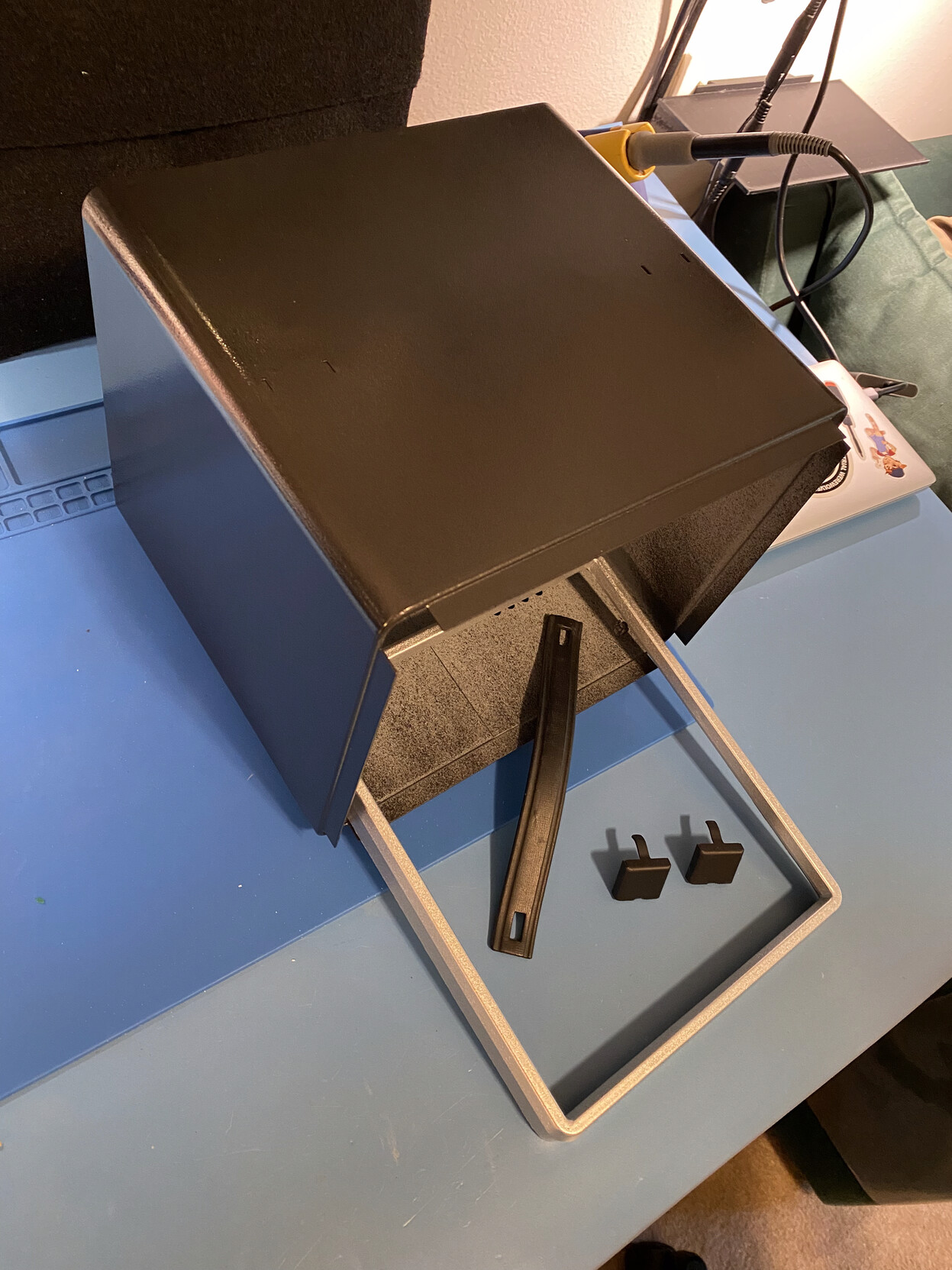
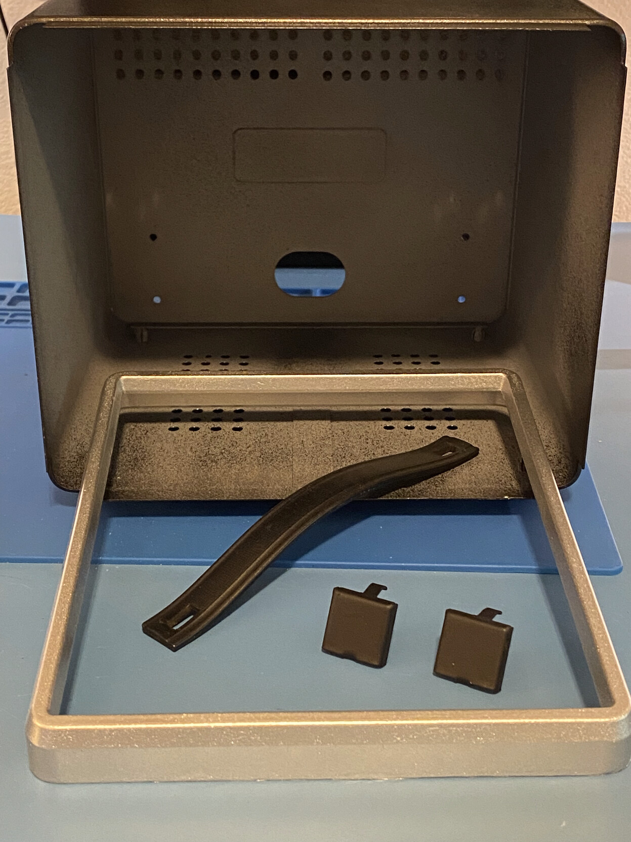
Three-quarters view, mostly about showing the case, but also the other parts.Front view, focusing on cast aluminium frame and handle parts
There. I also added alt-text for the images. Let’s see how this looks on Dreamwidth. Hopefully everything carries over!
Moving the ground coil away from the inductor coil (and also uncoiling it) helped... but only a little. A couple of milliamps and maybe like six volts? So I implemented my DC blocker with a bypass if it gets high enough voltage DC and tried it again, DC no more issues, AC reduced issues, plugged it into a GFCI...
...and it tripped in like an hour.
So I think I'm just done trying to make this GFCI-compatible.
I'm trying to figure out now what to do with this stupid thing - whether to keep it as a parts UPS, or what. I guess I could use it on a non-GFCI circuit, maybe for... idk, chonkyboi, my gaming PC? Maybe I'll do that.
that ups with all the voltage on the ground lead, the one we had to pull out of the server room because it was tripping the GFCI all the time
i am just
oh my god
i am dumb, like sack of hammers
like... hammer sack. hacky sack, but with hammers
i was looking at it today, trying to figure out good placement for my ground circuit modification and
the ground lead? the one with current on it? it's wrapped up in little loops in shrink insulation to save space
it's a decent number of loops, they used a lot of extra wire, i just thought it was a big ferrite but no
anyway, that big set of loops coiled up to save space, where does it live?
it lives next to the GIANT INDUCTIVE COIL AND INVERTER that is part of the power filtration circuit
like, _touching it_ close
and here i am, wondering why there is current on the ground lead
here i am, designing a circuit modification to block it
and here i am going no wonder it's so fucking variable by individual UPS because IT DEPENDS UPON WHERE THEY TIED UP THE EXTRA GROUND LENGTH DURING ASSEMBLY
i should say, in full transparency, that i haven't tested this yet and i don't even know if this will fix it but i'm pretty sure seeing INDUCTION on wire that is COILED UP NEXT TO AN INDUCTOR is a PRETTY GOOD CLUE for WHAT THEY DID WRONG
if this fixes it i don't even know what to think. other than hey, fixed ups?
Regarding the bad idea I posted yesterday, I've further realised I could build a rectifier too, then use a capacitor to block all of the leakage until the cap gets oversaturated (by actually serious/dangerous voltage) which turns it back into a ground again.
As before, on a scale of 1 to what the fuck is wrong with you, how bad an idea is this?
So in what might be a very dumb idea I've realised I can block the DC on the UPS ground with a good quality (say, 250V film) capacitor. It'd still pass the AC, but it'd contain the DC leakage until it gets so high that the capacitor bridges and it becomes a DC conductor as well. That would preserve the safety function of the ground pin, at least, in theory.
This is the UPS that occasionally trips GFCI. As far as I can tell, APC expects a percentage of its units to trip GFCI - they're more up front about this in documents meant for Europe, which implies they don't have good control over the issue. But this one's long past warranty.
(In Europe, the policy is not to answer questions but just replace the unit no questions asked... and hope, I guess, that the replacement is leaking less. It does seem to be rather variable. Our longer-term situation, fwiw, is going to be "fewer UPSes." As these old ones give out, we'll move to a single UPS for the tower. I don't like it, but it seems least problematic in the long run.)
On a scale of 1 to what the fuck is wrong with you, how bad an idea is this?
I need/want to do a complete teardown and rebuild of my Scuf controller (a PS4 Infinity Pro), and I'm thinking of streaming that live on twitch. You don't see that many people going into Scuf controllers, and, in particular, working on the paddles, despite the paddles getting stupid being a... feature? Recurring nightmare? Anyway, it's an issue. But it's like super fixable and I could show how.
In my case I'd be doing more - I want to put the original buttons that I took out to repaint back in, so it's going to be a top to button (lol) teardown.
The only problem with doing it this week like I really wanted to is that we have roofers working soooo... not probably so much this week. Probably next week instead.